Power Supply for a 4-cam Surveillance System
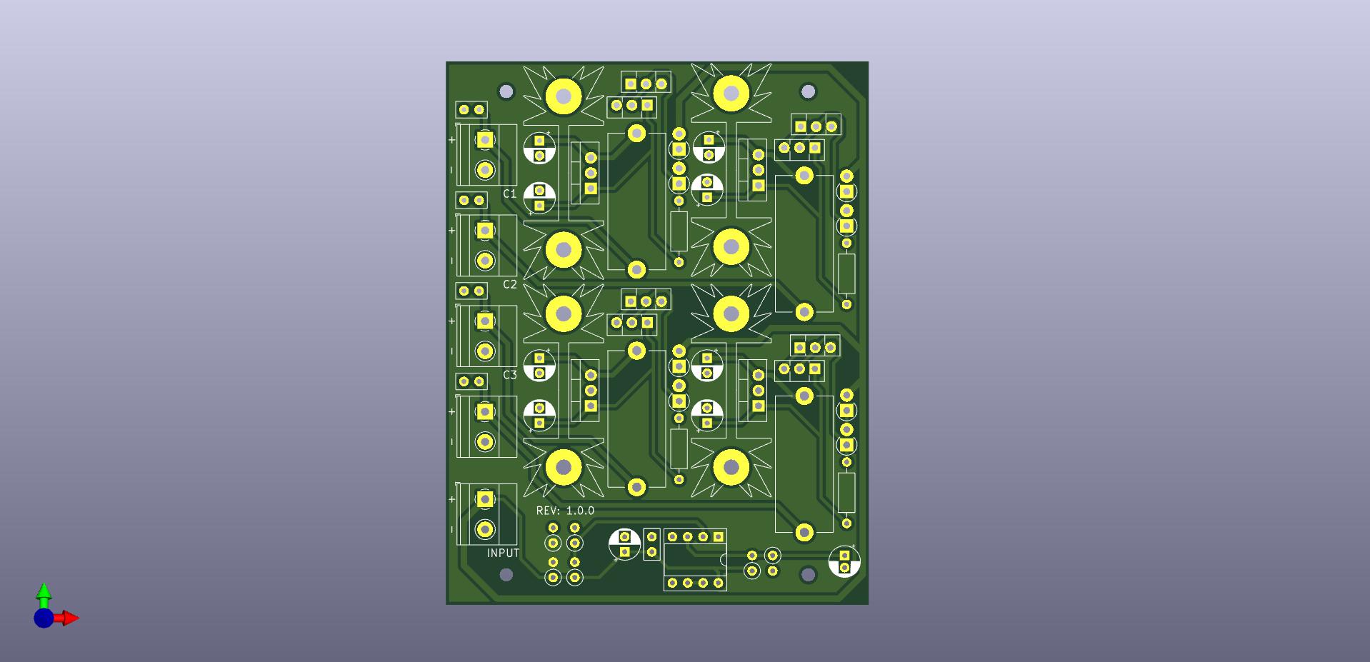
After purchasing a surveillance system that supported four analog CCTV cameras, I was presented with the problem of providing 12V DC to each one of them. I didn't want to spend additional money on overpriced adapters and extension cords in my local electronics store, so I decided to use components that I already had laying around to solve the issue presented to me. The goal was to make a PSU that would provide stable 12V DC to the cameras and offer some degree of protection, simplification of the cable management horrors was just a cherry on the top.
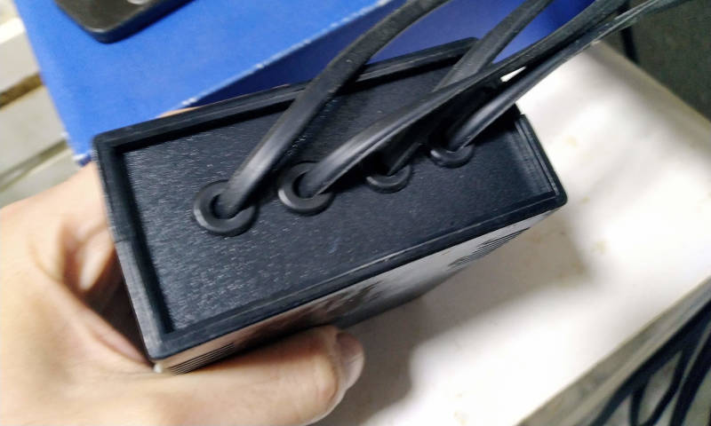
It probably seems a little bit strange, but if an entire surveillance system costs <100 euros - around 60 in my case, it makes very little sense to invest additional 100-200 in an extremely overpriced, and poorly made, DC wall-warts & extension cords needed to make the system work. Aside from that fact, the sheer amount of cables that I'd have to mange (or not by leaving them in a chaotic pile that would collect dust & hair) would be the stuff of nightmares.
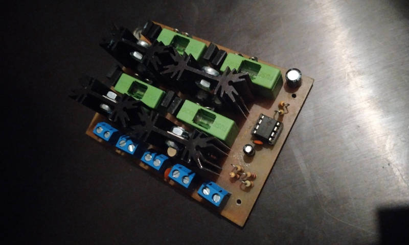
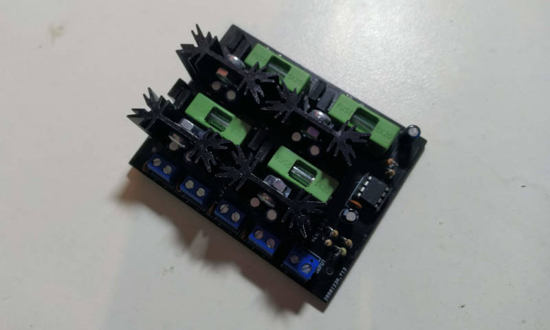
I had an old 19V laptop adapter able to supply 4A of current - perfect for the problem I was trying to solve, so I only needed to figure out how to drop its voltage safely to avoid burning the ancient LM7812 LDOs. The simplest solution was to use two rectifier 1N4007 diodes in series to drop around 2V and a Darlington pair to drop an additional 2V, bringing the input voltage down to safe ~15V. Darlington pair would also be used for preventing potentially high in-rush currents by controlling the base current using the jellybean LM393 comparator - an overkill and a typical case of over-engineering from my side I admit.
Dropping voltages using the "diode method" in the domain of Power Electronics is probably not a very good idea. The forward voltage of a diode will vary greatly with current and temperature - too low and the LDOs would burn out, too high and the LDOs may fail to regulate. In this particular case, it didn't matter a lot whether I'd drop 2 or 4 volts, large heatsinks were attached to the LDOs and the variation in VF was taken into the account.
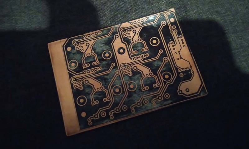
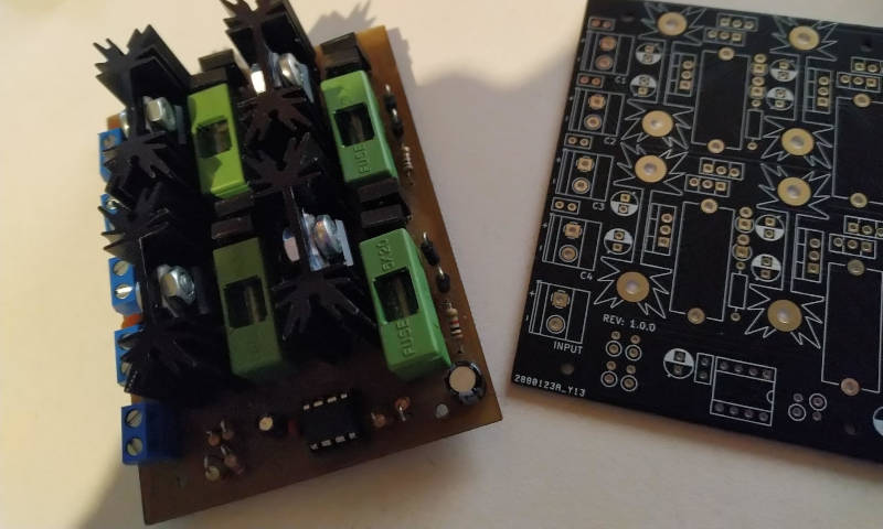
I was a bit impatient, and didn't want to wait for an entire month for the profesionally made PCBs to arrive. So, considering that the design was a fairly simple one, I proceeded with making a single board using the toner transfer method - which turned out better than I expected.
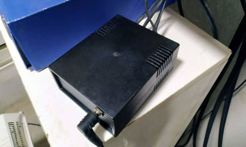
It's worth noting that the PSU remained active 24/7 from the day it was made (cca. May 2021) and has worked flawlessly ever since. Cost of the entire build - including parts, PCBs and the enclosure was roughly 30 euros which is definitely a "win" in my book.
Techincal Characteristics
- DC Input 16-24V
- 4x DC Outputs: 12V
- Max Output Current: 0.5A
- Output Ripple: <20mV
- Efficiency: ~75%
- Soft-Start Feature
- Short-Circuit Protection

