Enclosure Design for the Environmental Noise Monitor
After years of studying Circuit & Field Theory, designing custom PCBs was a logical step forward in that journey. Ability to design and manufacture compact and elegant 2 & 4 layer boards for less than a bag of chips, and have them shipped from China for almost no additional cost was definitely a dream come true for me. However, putting them to use in a day-to-day life proved to be a little problematic – dirt/dust (known to become conductive if left untended) was quick to collect on the bare PCBs, components got shorted and sometimes destroyed by the left-over leads beneath the PCB, etc.
Some PCB manufacturers were already offering 3D printing services for rapid prototyping, and I thought that my latest project, whose sole purpose is to monitor noise levels for long periods of time - months, would be a perfect excuse to try one of them out. A quick Google search on what Software to use for designing 3D printing parts yielded an unsurprising result – any CAD software for Mechanical Engineering that can generate OBJ files would suffice.
I went to a vocational High School for Computer-Aided Mechanical Engineering (that was a thing back in the mid-2000s here in the quasi-socialist "utopia" I live in) and was already familiar with CAD software like Catia. Couldn't have used Catia even if I wanted to though - because of their license, so I chose FreeCAD. It works perfectly on any Linux machine and doesn't require an active Internet connection - working on a box not connected to the Internet is my preferred way of doing things, it trumps any security policy and/or hardening you might think it'll help.
After a few days of learning the basics of FreeCAD, I managed to finish the design for my board, one that is extremely easy & cheap to manufacture – an entire 2.5$ including shipping to Serbia at one Chinese PCB manufacturer. The most difficult part of the design was probably the translation of the component XY positions from KiCAD to FreeCAD – the version of KiCAD I was using didn't have the ability to generate STEP files of a board and its 3D components so I had to do that manually, one component at a time.
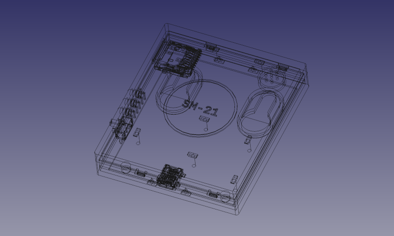
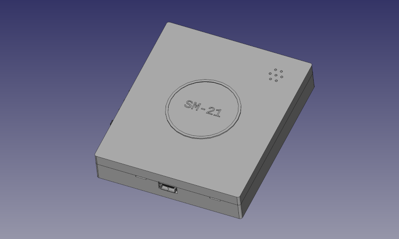
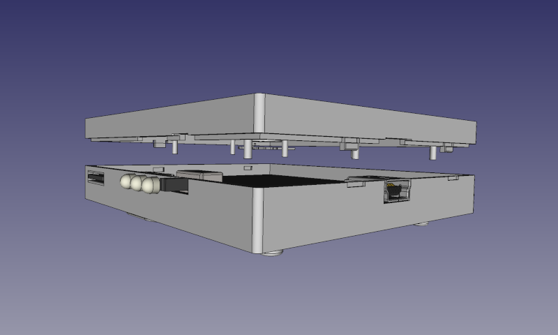
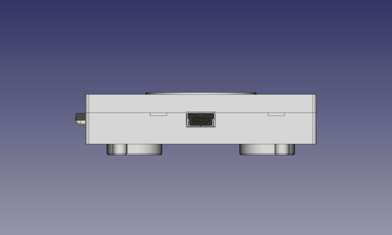
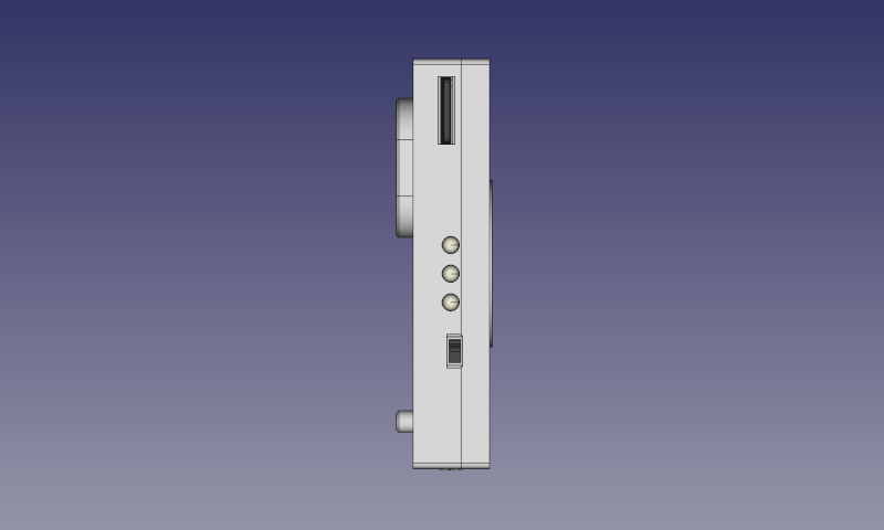
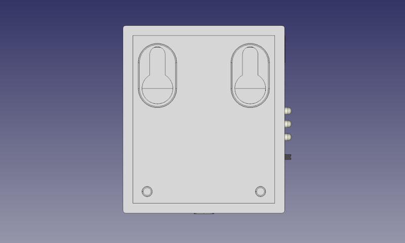
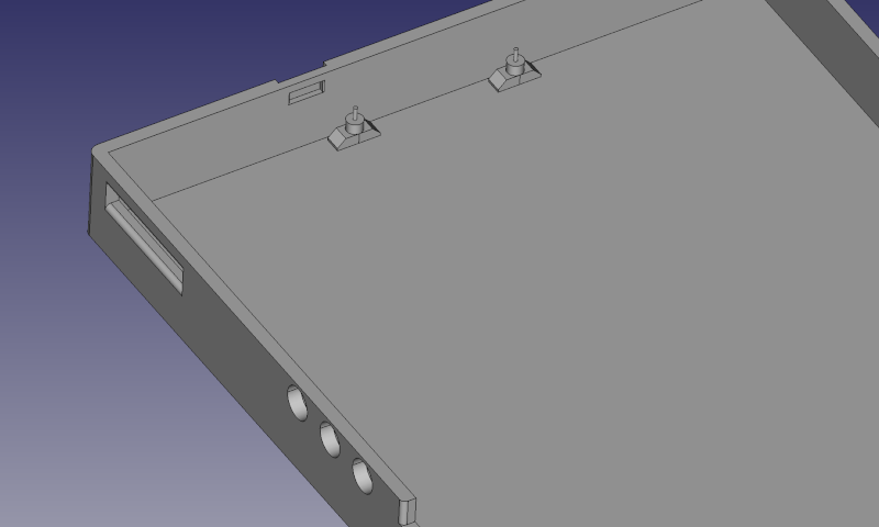
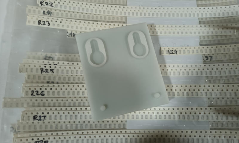
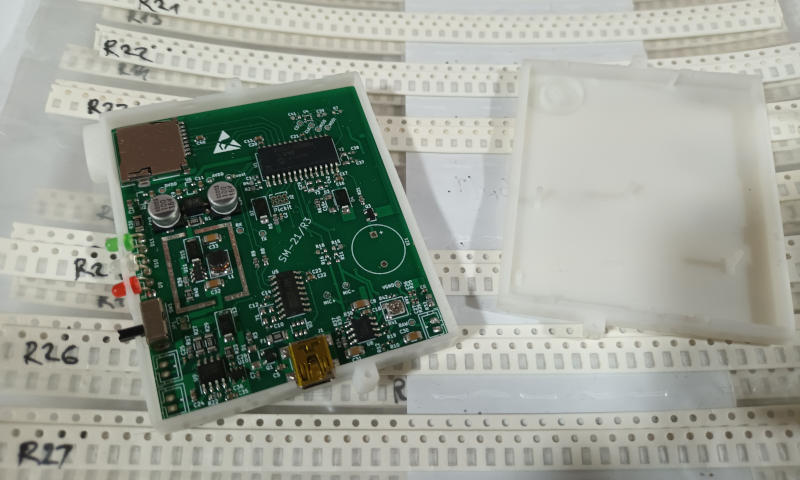
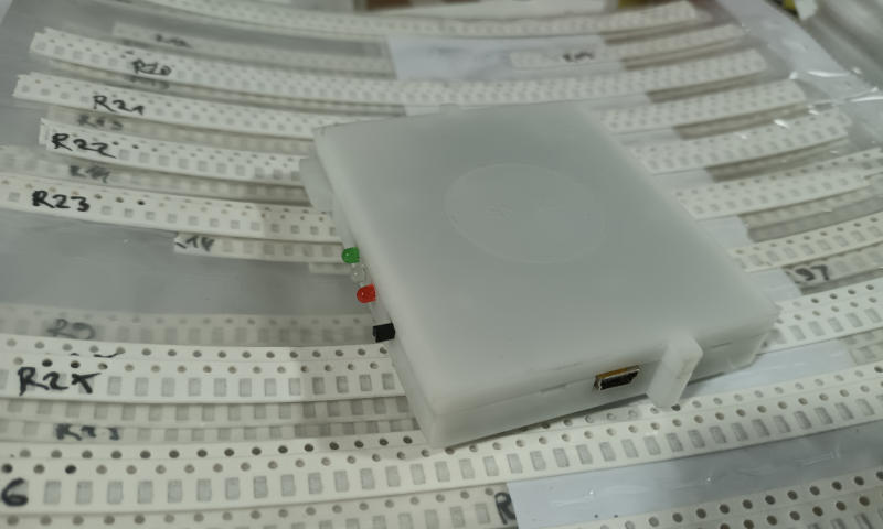
The design was inspired by the one used for Pickit 2 & 3, and it consists of only two parts that snap together. The top section contains extruded pillars that extend down to the PCB and hold it in place, while the bottom one has holes for mounting the enclosure to the wall and slightly more complex extrusions that keep the board slightly elevated and flush – some THT components were used in the design. Additionally, the design contains openings for indicator LEDs, slide switch, USB interface, and an SD card slot.
You may have noticed that extrusions intended to hold the PCB in the bottom section are slightly widened. Resin used for 3D printing is apparently extremely brittle, or so I thought initially. Slightly widening the extrusions was done to make them more durable and prevent them from breaking off.
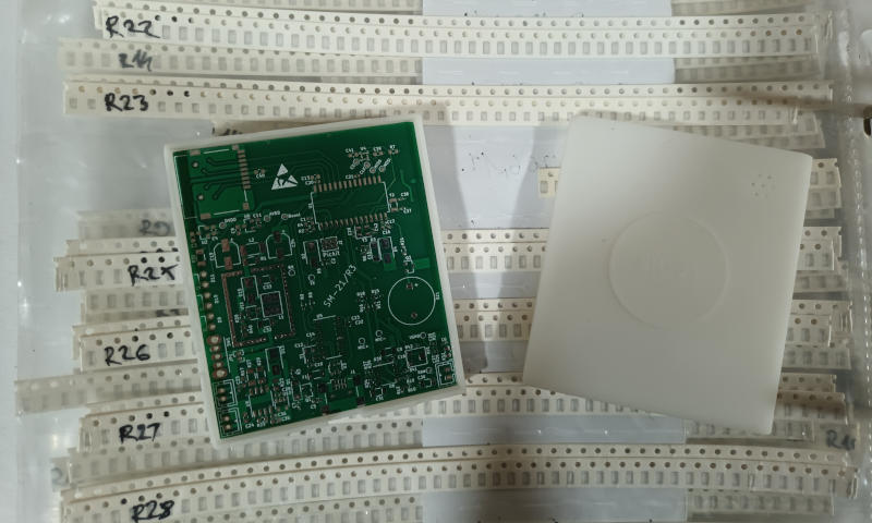
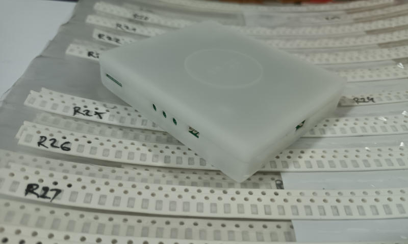
Enclosure, and a few of its variants, arrived one month after the order has been placed. The board fit neatly inside, the extrusions designed to keep it in place weren’t brittle as I expected them to be, and it almost felt like I had a real product in my hands after the complete assembly. I say almost because of that white and almost translucent resin used for 3D printing, and a few minor overlooks from my side - ones that I plan to amend in the next iteration made with a better quality resin.
