The importance of RF Jammers, or EW Exciters as they are called in literature dealing with the subject of Electronic Warfare, will only continue to grow as technology advances in the coming years. Threats to personal security from commercially available drones - that keep getting cheaper from year to year, and personal privacy from ever-connected eavesdropping and tracking devices we willing bring into our lives are but a few contributing factors.
Believe it or not, there's a big market for RF jammers in Serbia, and some "military-grade" ones are being sold for several thousand euros - which comes as no surprise to anyone familiar with the situation in the quasi-socialist "utopia." From time to time broken ones pop-up on online markets that I promptly purchase for fraction of their worth to reverse engineer and scrap for parts - antennas, power amplifiers (5W VGA being my biggest score), and VCOs.
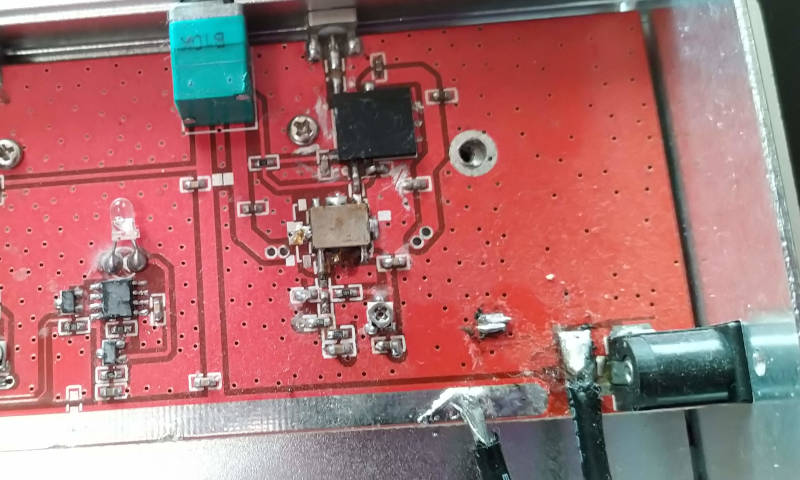
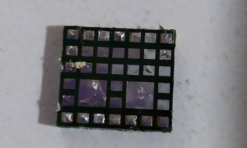
They are in most cases imports from China, some extremely poorly made, with chip details scratched off to make reverse engineering slightly more difficult - like in the following example.
Building Blocks
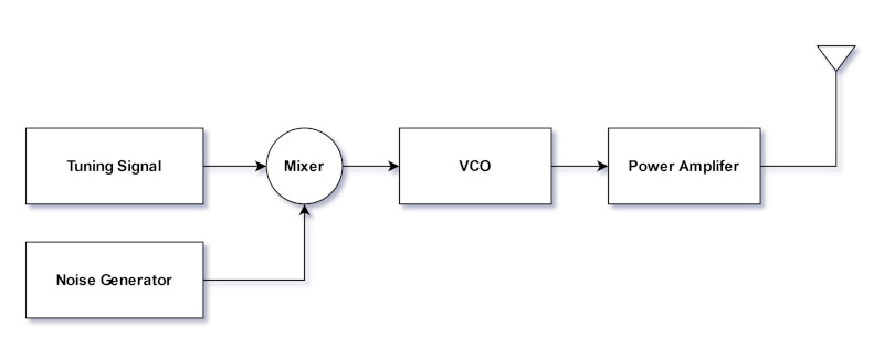
There are only so many ways one can make a jammer, and the designs I reverse engineered usually followed the same pattern. Triangle Wave generated by a 555 timer is DC biased and fed to the VCO. From there, VCO generates a Frequency Sweep in the desired range that gets amplified, and that's basically it.
Tuning Signal
Tuning Signal can be generated in a variety of different ways. A Square Wave generated by a basic Astable Multivibrator, or 555 Timer, can be transformed into a Triangle Wave of the desired amplitude. A Relaxation Oscillator can be made using dirt-cheap and readily available logic ICs or Op-Amps. If money isn't an issue, and you are willing to go with an analog-digital design, you can even use a DAC.
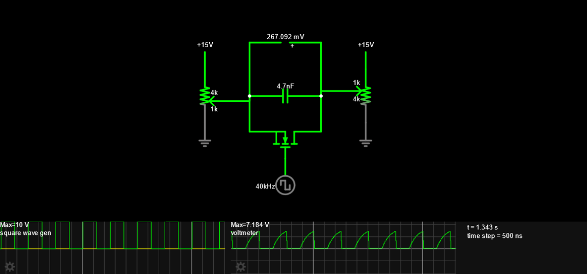
There was a case where I saw CMOS Analog Switch (74HC4066) used to generate an "imperfect" Sawtooth Wave by setting the voltage of the top/bottom plate of a capacitor using two potentiometers and connecting them to the input/output of the switch respectively. Continuous charging/discharging of the cap was done using a 40kHz Square Wave fed to the enable pin of a switch - a typical case of over-engineering in my opinion but a very clever way of generating a Sawtooth Wave of arbitrary amplitude.
Simulation on Falstad can be found by clicking here.
Noise Generator
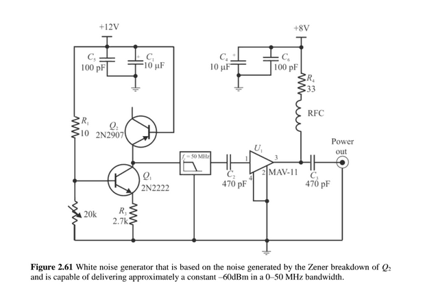
Noise is everpresent, and it can be generated with or without the use of an active device. Exploiting the properties of Thick Film resistors, Avalanche Effect in Zenner diodes, or combining PNP and NPN transistors like in the following example - taken from the book on Electronic Warfare (link in the end) are all potential solutions.
Mixer
It is interesting to note that none of the commercial jammers I had a chance to work with modulated the Tuning Signal with Noise - to alter the predictable pattern of the Frequency Sweep and improve the effectiveness of a Jammer. A simple summing amplifier, or even current summing using two basic resistors - to keep things simple, would greatly improve their performances. It may seem redundant, but the math doesn't lie.
Effectivness
When I was trying to find any Mathematical model that could help me understand how the Tuning Frequency, Tuning Amplitude, and other VCO parameters affect the effectiveness of an RF Jammer, I couldn't find any. Is it better that the Tuning Frequency is higher or lower? What about the Q factor? How important of a role does the Amplitude of a Tuning Signal play - if any? I had to put on my thinking hat and find out by myself.
I asked myself how would the parameters of an RF Jammer affect the number of dropped packets in a basic OOK Transmitter under the assumption that the P(jammer) > P(transmitter).
- Tuning Frequency (FT) is inversely proportional to the number of dropped packets
- Tuning Range (FR) of a VCO, being the frequency range between the upper and lower frequency that a VCO can generate, is inversely proportional to the number of dropped packets
- Baud Rate (B) is proportional to the number of dropped packets
- Receiver Bandwith (BWRX) is proportional to the number of packets dropped
- Tuning Amplitude (VT), that is the amplitude of an AC signal used for tuning the VCO, is inversely proportional to the number of packets dropped
- Noise (VN) present in the tuning signal is proportional to the number of packets being dropped
- Tuning Sensitivity (TS) is proportional to the number of packets being dropped

|

|
| NDP Equation | Effectivness Equation |
The effectivness can then be represented as a ratio of the transmitter's Baud Rate and the approximate number of Dropped Packets.
Power Output
In academic literature dealing with Electronic Warfare, you may find complicated equations used for calculating the power output needed for an EW Exciter to jam the desired signal. Such literature usually deals with complicated radar systems used by military personnel and applying them in scenarios where a regular person wants to ex. protect their property from unwanted drones, or in closed public areas during events where disturbance from mobile devices can cause disruption is usually overkill. Having an amplifier capable of 20+ dB signal amplification, and as high compression point as possible, coupled with a decent antenna is usually more then enough in such circumstances. 2.4GHz amplifiers that offer 40dB gain are extremely common, readily available and relatively cheap - 1-2 euros per unit.
If you're interested in learning more about the subject, I highly recommend the RF Electronics for Electronic Warfare by Poisel that's freely available on Google Books.
