Being able to measure unknown inductance is arguably important in a lab setting whether you are a professional or a hobbyist. Dedicated LCR meters and multimeters that can measure inductance are often way to expensive for someone that has just entered the world of electronics, so this article will cover the least expensive way to find inductance using DSO Shell oscilloscope (usually the first oscilloscope of an average hobbyist) and a basic 555 timer circuit.
Other than a DSO Shell oscilloscope, which can usually be picked up for ~20$ already assembled, following components are required for the circuit:
- 1x Copper clad board or perfboard with copper pads
- 1x NE555 timer
- 1x 1N4007 diode (any rectifier or schotkky diode should work)
- 1x 670 ohm resistor (0.25W)
- 2x 10k ohm resistors (0.25W)
- 1x 1μF capacitor
- 1x 33μF capacitor
- 1x 1000μF capacitor
- 2x pins (for attaching the scope, you can use a thicker pieces of copper wire instead)
- 1x 2-pin socket (RM2.54mm)
The total price of the listed components at my local electronics store was ~1.5€ but considering that it is generously inflated due to import fees you can expect it to be much lower in your country.
Idea behind the circuit is to generate damped oscillations using the LC tank circuit consisting of an unknown L, capture them using the oscilloscope, and determine the value of an inductor using the formula for calculating the resonant frequency of an LC tank circuit.
|
|
|
|
| Resonant Frequency | Inductance (L) | Capacitance (C) |
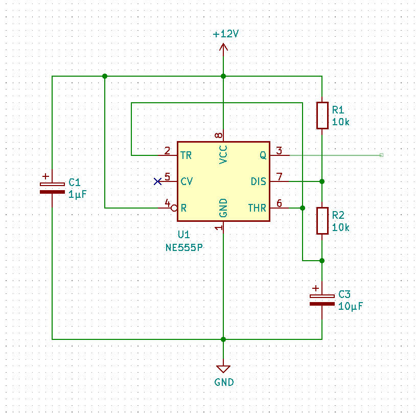
For that you'll need to generate a stable square wave signal using the 555 timer - basic astable multivibrator will do the trick.

|
| 555 Timer - Astable Configuration |
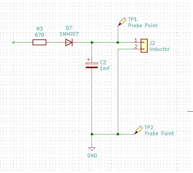
Load of the multivibrator should look like this.

|
| 555 Timer - Load |
670 ohm resistor limits the current drawn from the output to a safe level, diode prevents the timer from discharging the capacitor in the off cycle which can prevent the oscillations from happening - remember that 555 can both source and sink 0.2A of current, and the rest is self explanatory.
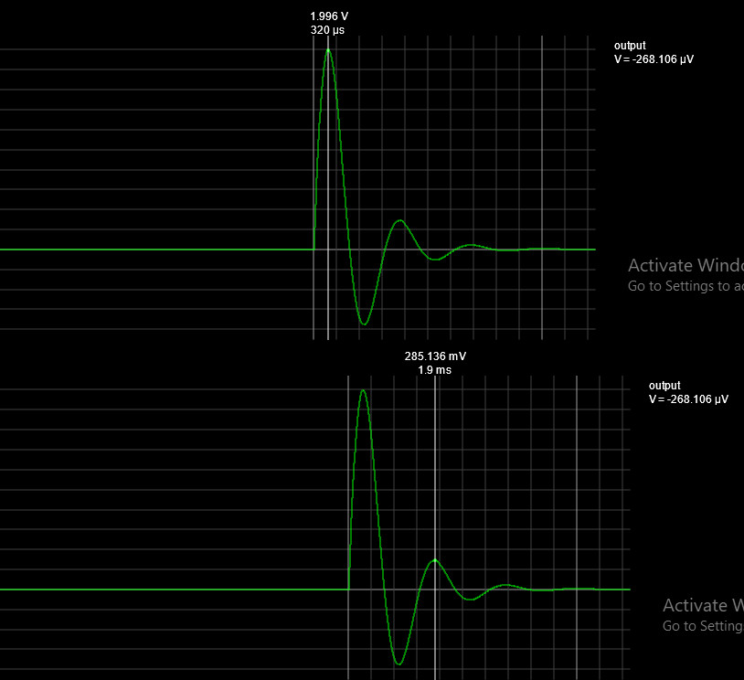
If you did everything right, the oscillations viewed from DSO shell should look like this.

|
| Damped Oscillations |
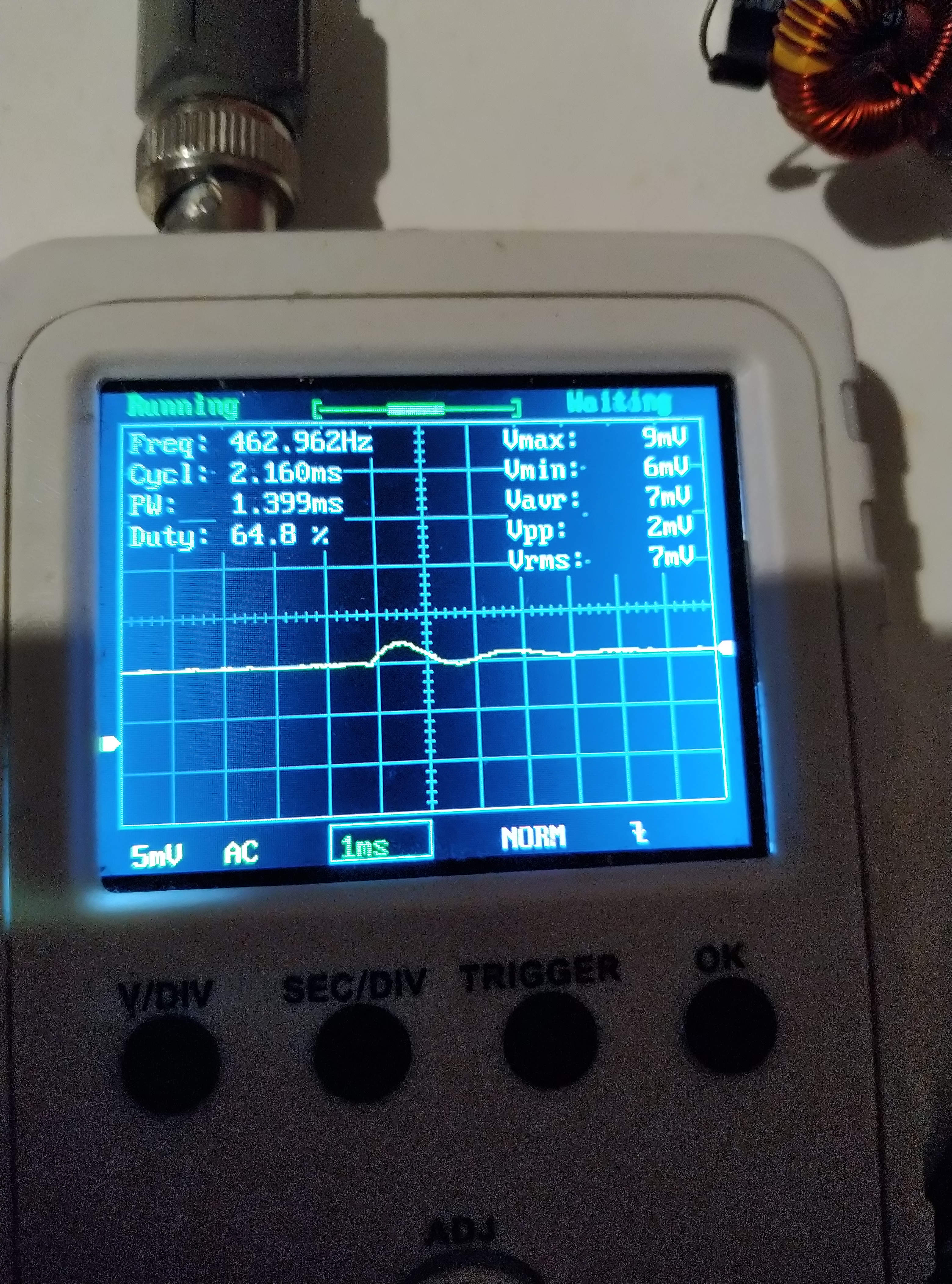
Normaly you would use the time difference between the two peak values, calculate the frequency, and after that inductance using the formula listed above. Luckily, DSO Shell will determine the frequency automatically and display it in the overlay screen - activated by pressing and holding "OK" for a few seconds.
To capture the oscillations and determine the frequency, you need to:
- select AC coupling
- set V/Div to 5mV
- set trigger mode to NORMAL
- position trigger level slightly above 0
- set trigger edge to falling
- set Sec/Div to an appropriate value - it's a 20$ scope so you need to fiddle around a bit, I found that Sec/Div should be roughly equal to half of the 1/F, too big of a division will yield invalid value, too low of a division will not yield any value

|
| DSO Shell - Capture |
And from the results, we can easily calculate the inductance of 120μH.