PIC has been manufacturing microcontrollers with built-in DACs for quite some time now, and I thought that an article on generating arbitrary waveforms using nothing more than an MCU, PIC18F45k50 in this particular case, would be useful to the newbies.

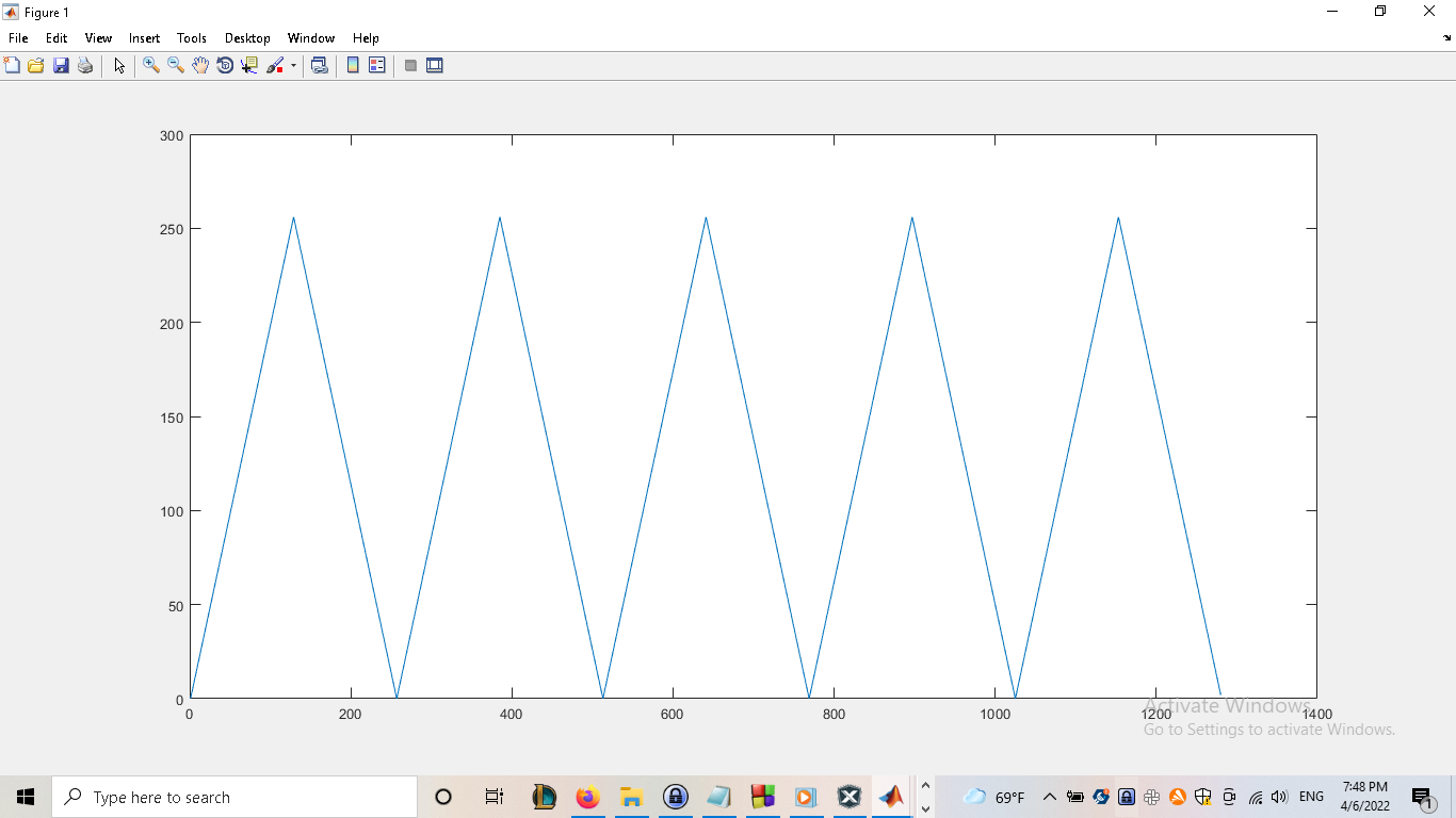
Image 1 - 8-bit Triangle Wave
Basic, and keep in mind unoptimized, library would consist of only a few simple functions. Function "vtob" would be used for converting voltages from the human-readable form ex. 2.5 to its "binary" representation that could be pushed to a device's register - VREFCON2 register for PIC18F45k50.
Function "sin_map" would generate an array containing values needed for producing a continuous sine wave, and the "print_map" function would print the values of an already generated map for use-cases requiring lower RAM footprint ie. storing the map as a constant in the program memory.
// Function Definitions

int dac_vtob(float);
void dac_sin_map(int*, int, float, float);
void dac_print_map(int*, int);
The library should be easily customizable to accommodate a variety of different devices. The following block contains definitions for reference voltage, DAC resolution, and size of the signal map buffer.
// Library Configuration

#define DAC_PI_N     -3.14
#define DAC_PI_P      3.14
#define DAC_REF       5
#define DAC_RES       5
#define DAC_BUFFER    32
Basic conversion function as described in one of the previous paragraphs.
/**
  * @param v
  *     Human-readable foltage ex. 2.5
  * @return int
  *     Binary-representation ex. 16 for a 5-bit DAC using a 5V reference
  */
int dac_vtob(float v) {
    return (int)((v / DAC_REF) * pow(2, DAC_RES));
}
When dealing with low-resolution DACs, you can get away with using a small buffer ex. 16-byte buffer when dealing with a 5-bit DAC.
/**
  * @param *buff
  *     Pointer to a buffer in which the map will be stored - memory must be pre-allocated
  * @param len
  *     Size of the buffer ex. 128
  * @param dc_off
  *     DC offset of the signal ex. 2.5
  * @param ac_vpp
  *     Peak-to-peak voltage of the signal ex. 1.0
  * @return void
  */
void dac_sin_map(int *buff, int len, float dc_off, float ac_vpp) {

    int   i = 0;
    float j = DAC_PI_N;

    float incr = DAC_PI_P / (len / 2);

    dc_off = dac_vtob(dc_off);
    ac_vpp = dac_vtob(ac_vpp / 2);

    do {

        buff[i] = (int)(ac_vpp * sin(j) + dc_off);

        if (buff[i] < 0) {
            buff[i] = 0;
        }
    }
    while (i++ < len && (j += incr) < DAC_PI_P);
}
If RAM is at a premium, you can compile the library with GCC and pre-generate signal maps to store them as constants in the program memory of your device.
/**
  * @param *buff
  *     Pointer to a buffer in which the map is stored
  * @param len
  *     Size of the buffer ex. 128
  * @return void
  */
void dac_print_map(int *buff, int len) {

    for (int i = 0; i < DAC_BUFFER; i++) {

        if (i == 0) {
            printf("x = [ %d", buff[i]);
        }
        else {
            printf(", %d", buff[i]);
        }
    }

    printf(" ];");
}
The frequency of the generated signal is ~600Hz in the snippet below, and can be easily adjusted by tweaking the value of the XC's "__delay" function, or by altering the buffer size.
|
|
| Output Frequency |
// Basic Implementation

int buffer[DAC_BUFFER];

dac_sin_map(&buffer[0], DAC_BUFFER, 2.5, 4);

while (true) {

    VREFCON2 = buffer[i++];

    if (i == DAC_BUFFER) {
        i = 0;
    }

    __delay_us(100);
}
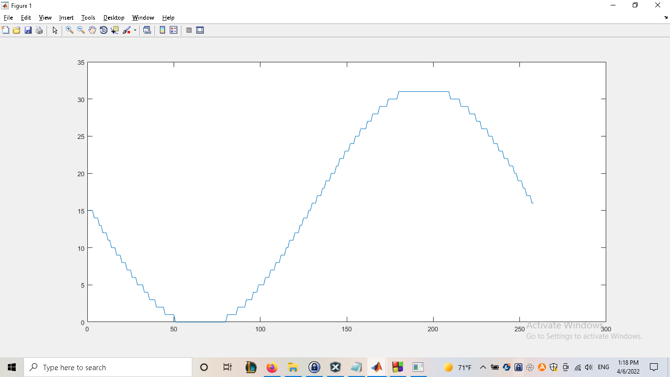
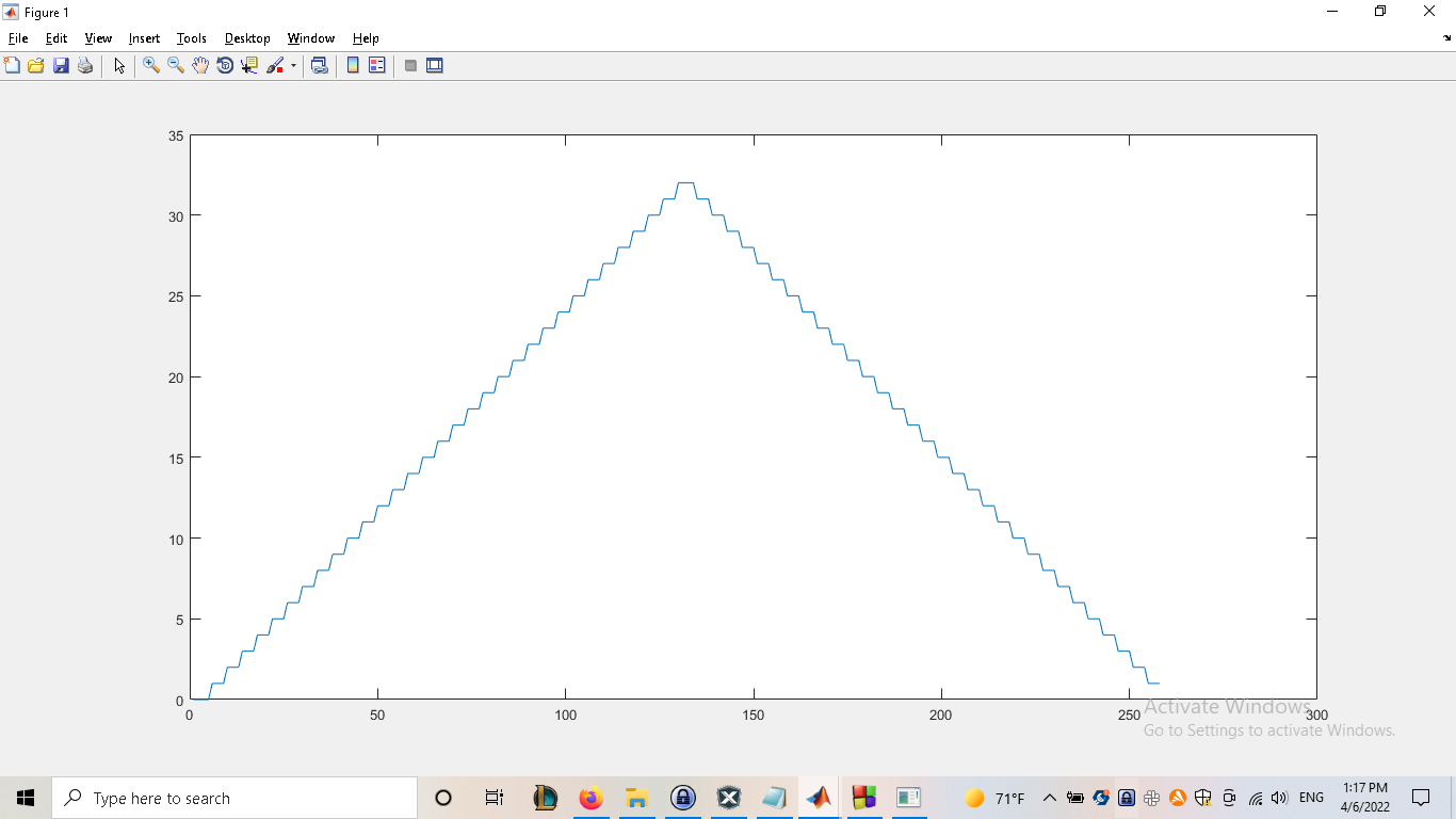
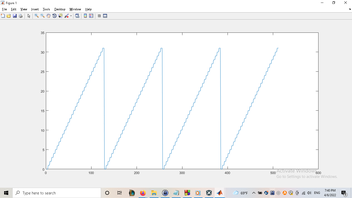
Here are some previews of the signals that could be generated using a 5-bit DACs on 8-bit microcontrollers.


